Contributors: Kate Hartman, Hazel Meyer, Ken Leung, Oldouz Moslemian
Funding: OCADU Corus Seed Grant
Keywords:
Tools:
Super Heroes shouldn’t always have to save the world all on their own. Occasionally they need to call on their Super Hero friends for a little back up.
The Superhero Communicator Cuffs enable brave souls to call on their partners in a time of need. This tutorial demonstrates how to send and receive wireless signals without the use of microcontrollers or programming. You will learn how to configure Xbee radios, build a basic soft circuit, and work with conductive thread and conductive fabric.
How it works: Each pair of cuffs has an electronic switch made of conductive fabric. When the wrists are crossed, a wireless signal is transmitted which activates the LED on your partner’s set of cuffs, beckoning to them that you need Super Hero assistance! Since you’ll be making two pairs of communicator cuffs, this tutorial will be great to make with a friend!
Parts and Materials

(3.7 volts,900mA or 1000mA is good)

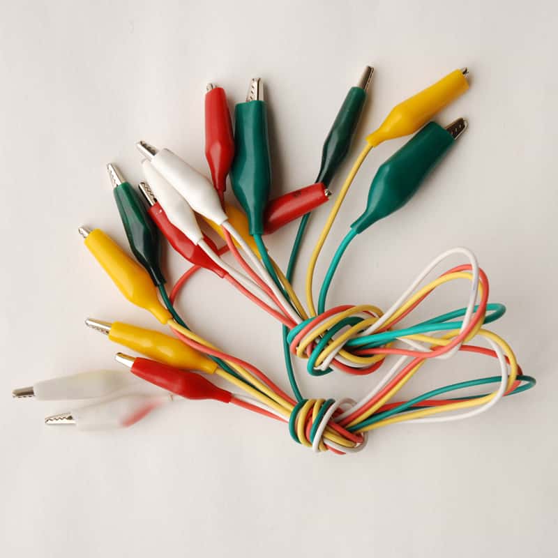
*Make sure you have 2 of these items if you’d like to perform Chat Testing in Step 8
Tools
You will need a computer with FTDI Driver and CoolTerm installed (ideally two computers).
What is the Lilypad Arduino & Xbee?
The Lilypad Arduino is a wearable, sewable version of the Arduino Microcontroller board. In addition to the Lilypad Arduino, there is an entire body of Lilypad components that you can incorporate into your wearable projects. In this tutorial you will be using Lilypad LEDs along with the Lilypad Xbee board.
The Lilypad Xbee is a wearable, sewable breakout board for an Xbee radio. It has Digital Input/Output pins and a voltage regulator, among many other useful features. For detailed information about the Lilypad Xbee, see here: http://lilypadxbee.katehartman.com/about-board/
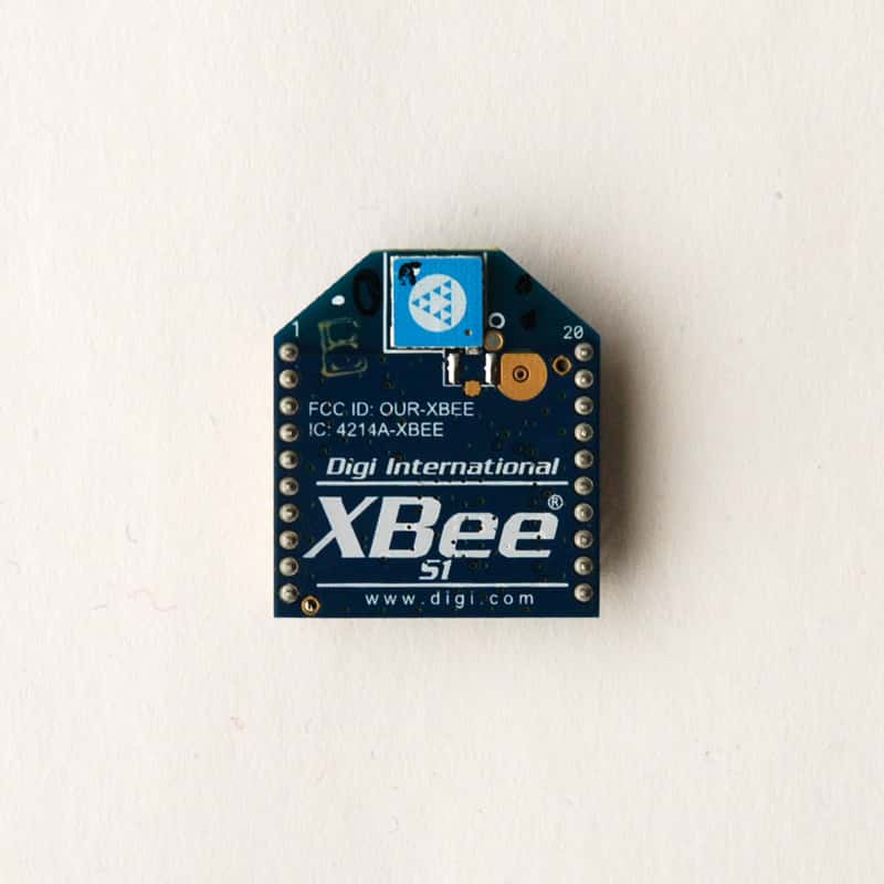
Xbees are a small wireless radios that can send and receive data. They can be used in pairs, multiples or networks, both with and without a microprocessor (such as Arduino), and are generally a reliable and easy-to-use wireless communication option. You can find out more about them here: http://www.digi.com/products/wireless-wired-embedded-solutions/zigbee-rf-modules/point-multipoint-rfmodules/xbee-series1-module.jsp#overview
Step 1: Prepare the Lilypad Xbee
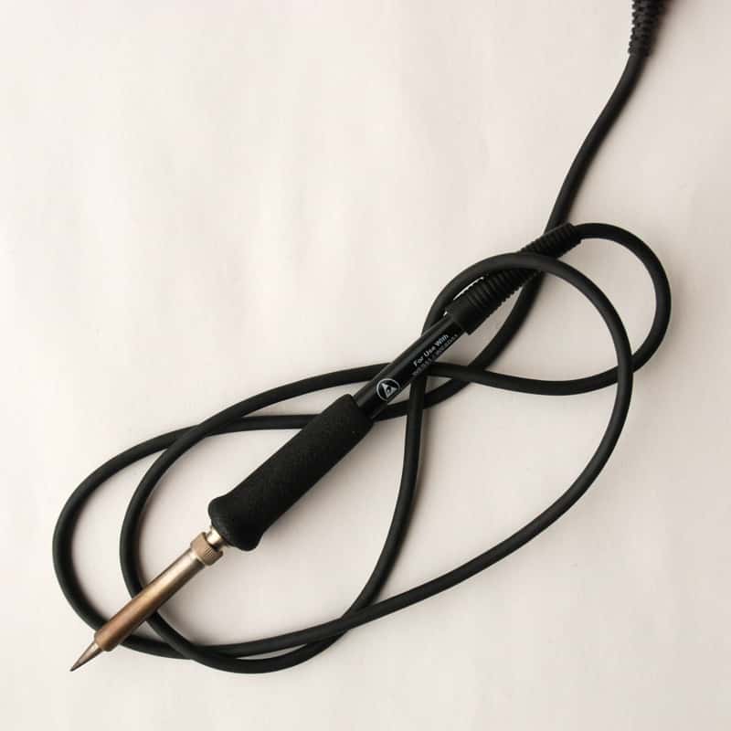
Solder the 6-pin right-angle Male Headers onto the Lilypad Xbee board, as illustrated in the photo. If you’re new to soldering, check out this soldering tutorial: http://video.google.com/videoplay?docid=-1438613870956797134#
Step 2: Download and Install the Software
Download and install the following software for your operating system: Coolterm (a freeware available for both Mac and PC computers) http://freeware.the-meiers.org/ FTDI Driver http://www.ftdichip.com/FTDrivers.htm (If you already have Arduino installed, you likely have the FTDI Driver installed as well. It comes with the Arduino Software package.) *Once you have installed these items, be sure to re-start your computer.
Step 3: Label The Xbees
Before configuring the Xbees, first label them so that they are easier to distinguish. We’ve labelled one XBee with green tape, and the other XBee with pink tape. These colors will be used to identify the XBees for the remainder of this tutorial.
Step 4: Configure the Xbees
To enable our two XBee’s to communicate, they must first be configured so that they know how to send information to each other. To do this we’ll be using CoolTerm, a terminal program which allows you to communicate with hardware connected to your serial port.
a) Plug your GREEN Xbee into the Lilypad Xbee board, using the visible guide lines inscribed on the board. Ensure that the pins are properly lined up, and that the Xbee is not plugged in upside down. Connect the FTDI Breakout board to the male headers on the Lilypad Xbee board and plug in the USB cable to both the board and your computer.
b) On a Mac: Go to your Applications folder and open CoolTerm.
On a PC: Go your the directory where you installed Coolterm, and click CoolTerm.exe
c) In the Menu bar, select Connection > Options. Under the ‘Serial Port’ tab on the left, select a Baudrate of ‘9600’. Then, under the ‘Terminal’ tab, turn ‘Local Echo’ on by checking the box.
Step 5: Configure the GREEN XBee
XBee radios are configured using commands called “AT Commands”. Before AT commands can be executed, the XBee must first be put into ‘Command Mode’. You can do this by typing ‘+++’ into the Coolterm window, which it should respond to with an ‘OK’ message. Do not click the <ENTER> key afterwards, or it won’t work! Note that Coolterm will exit from Command Mode in less than 30 seconds, so try not to leave the window idle. If you aren’t getting an ‘OK’ in response, type in ‘+++’ again to re-enter Command Mode.
a) For two XBees to talk to each other, they must have the same PAN ID. To set a PAN ID of say, 3456, you would type:
ATID3456
<ENTER>
You should then receive an ‘OK’ message — if not, make sure you’ve pressed <ENTER>, and also that you’re still in Command Mode). You can check your PAN ID at any time simply by typing ATID (with no parameters). NOTE: If you are in a setting where many pairs of Xbees are being configured to talk to each other, EACH PAIR must have a different set of PAN IDs.
b) Next, let’s set up a ‘my id’ for our specific XBee. To set a ‘my id’ of 2 for our first XBee, type:
ATMY2
<ENTER>
To check if this worked, simply type ‘ATMY’ — CoolTerm should echo back ‘2’.
c) We need to prepare the first XBee so that it will be able to the second XBee. To do this, we need to set a ‘destination ID’, by typing:
ATDL1
<ENTER>
This will set the destination device to ‘1’.
d) To save the configurations we made, type:
ATWR
<ENTER>
This is an important step. If you don’t write the settings to the Xbee, all settings will be deleted after the XBee is unplugged!

e) Click the ‘Disconnect’ button in CoolTerm to end the session, and then unplug the XBee from your computer.
Step 6: Configure the Second (PINK) Xbee
a) Unplug the USB from the computer. Remove the GREEN Xbee from the Lilypad Xbee board and plug the PINK Xbee into the board. Then plug the USB cable back into your computer.
b) In Coolterm, select the “Connect” icon in the Menu bar. From here, you will continue with the same steps as with the GREEN Xbee, except that you will change the following parameters:
| Cuff A (GREEN) | Cuff B (PINK) | Function |
| ATID3456 | ATID3456 | Sets PAN ID (same for both cuffs) |
| ATMY2 | ATMY1 | Sets individual IDs |
| ATDL1 | ATDL2 | Sets ‘Destination Low’ address |
| ATWR | ATWR | Saves all the data to the Xbee |
Your screen should look like this:

Step 7: Chat Testing
If you have two computers AND two FTDI Breakout boards available, you can test your “chat” abilities between the two Xbees.
a) To do this, plug the Xbees into the Lilypad Xbee boards. Then plug the FTDI Breakout Boards into the Lilypad Xbee boards, and connect them to the computers using your mini-USB cables.
b) On each computer, open Coolterm if it is not already open.
c) Select ‘Connect’ in the Menu bar.
d) Select Connection > Send String . Using this Send String function, you can send messages to each other’s computers, just like in the image below:
Step 8:
Once you have confirmed that your Xbees are talking to each other, you need to go back and add a few more configurations in Coolterm.
a) Click ‘Disconnect’ in the Coolterm window. Unplug the USB cable from the computer. Unplug your PINK Xbee and plug in your GREEN Xbee. Plugin the USB cable. Click ‘Connect’ in Coolterm.
b) Type ‘+++’ in the main window. Coolterm should echo back ‘OK’.
c) Now add the following configurations, starting with the GREEN cuff:
| Green Cuff | Pink Cuff | Function |
| ATD45 | ATD43 | Sets Digital I/O pins |
| ATD63 | ATD65 | Sets Digital I/O pins |
| ATIR64 | ATIR64 | Sets the sample rate to 100 milliseconds (Hex64) |
| ATIT1 | ATIT1 | Sets the number of samples before transmission to ‘1’ |
| ATIA2 | ATIA1 | Sets I/O input to Destination Address |
| ATWR | ATWR | Writes the configurations to the Xbee |

d) Once you have configured the GREEN Xbee, click ‘Disconnect’, unplug it from the board and plug in your PINK Xbee. Continue from step ‘b’ (above), to configure the PINK Xbee, using the settings in the above table.

Step 9: Second Chat Test
a) Plug each Xbee in their boards, and connect the GREEN Xbee to one computer, and the PINK Xbee to the other.
b) On each computer, open Coolterm if it is not already open.
c) Select ‘Connect’ in the Menu bar.
d) Select Connection > Send String . Just as before, you should be able to “chat” back and forth between the two Xbees/computer setups using the SendString function.
Step 10: Soldering the Lilypad Simple Power Board
When you first use the Lilypad Simple Power board, you need to make a small solder bridge using the two solder pads seen here:
For this tutorial we are using rechargable LiPo (Lithium Polymer) batteries. They are lightweight, small, and good for the environment, too. LiPo batteries have JST connectors (plastic plugs) that will snap into the Lilypad Simple Power board, which makes for a secure connection. In addition, the Lilypad Simple Power board has an ON/OFF switch which is great for conserving power.
Step 11: Alligator Clip Test
Now that your Xbees are configured and your power switch is ready to go, you can test your circuit using alligator clips. The connections are made according to this photo:
a) Trace the Lilypad Xbee boards onto your scrap felt fabrics. You will use these as “coasters” beneath the Lilypad Xbee boards so that the alligator clips do not slide around.
b) You should be able to turn on the LED on the PINK Xbee circuit by touching the leads of the alligator clips from the Ground pin ( — ) and D4 on the GREEN XBee circuit. You can do the same test for the LED on the GREEN Xbee circuit by touch together the Ground pin ( — ) and D6 on the PINK XBee circuit.
Troubleshooting the Alligator Clip Test: If the LED does not turn on, check the following:
- Is the LED polarity correct? (‘+’ goes to 3.3v, and ‘–’ goes to your output pin) Is the battery connected?
- Is the switch on the Lilypad Simple Power boards turned ON?
- Did you solder the pads on the Lilypad Simple Power boards? ( Step 8 )
- Are all the connections with the alligator clips properly made?
- If none of the above appear to be the problem, go back and double-check all of your Xbee settings using Coolterm.
Step 12: Sketch the Design Layout
Using pen/pencil and paper, sketch out how your design will look on paper. This is an important step, since when working with conductive thread you need to ensure that your connections are not crossed. The best way to avoid this is to work from a pre-planned design layout. If your Super Hero energy levels are not operating at full force today, you can download and follow along with our design layout here:
SuperHeroCuffs_Design (PDF)
Working with Conductive Thread
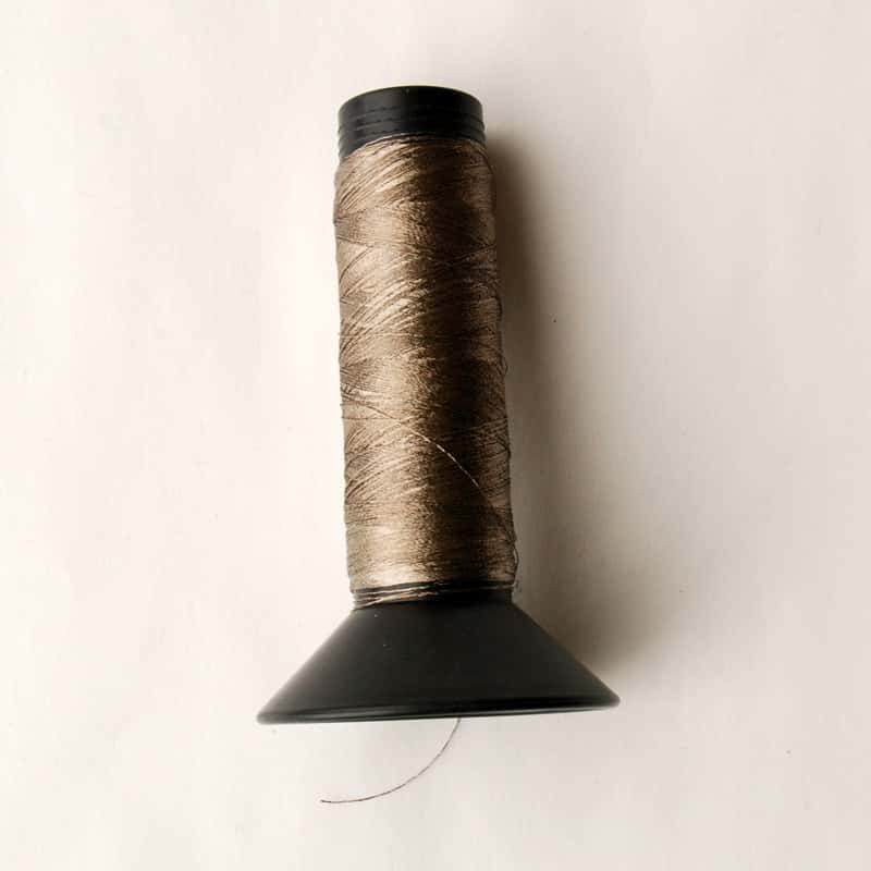
Conductive thread has many unique properties that need to be considered when using it in soft circuits. Here are some things you should know:
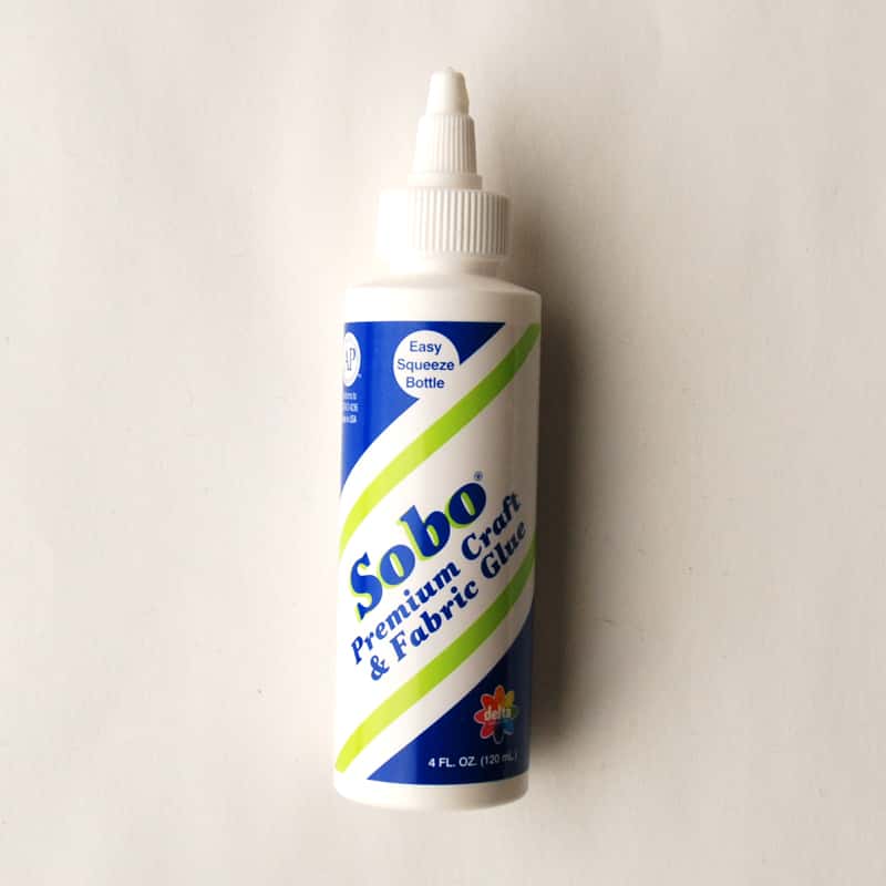
- Conductive thread is very slippery. Knots can have a hard time staying put, so try securing them with a bit of fabric glue or a dab of glue from a hot glue gun.
- Conductive thread acts more like wire than “normal” thread. Electricity runs through the lengths of conductive thread, so each connection (to a component, to your Xbee board) needs to be made of individual pieces of conductive thread.
- Because electricity passes through conductive thread, you want to make sure you don’t have any crossed connections. Look carefully at all of your connections before powering up your cuffs.
- If you need to intentionally cross over thread in your design, use the layer of felt/fabric as your insulator to make sure the two pieces of thread do not touch. See the image below:

Step 13 : Construct the Cuffs
a) First you will need your four rectangular pieces of 10” x 6” fabric. In this tutorial we have used a heavy green felt for one set of cuffs, and a heavy pink felt for the second set of cuffs.
b) Next, sketch out your awesome Super Hero design onto the back of your pre-cut pieces of conductive fabric. Keep them a large enough size for easy contact.
d) Iron these conductive SuperHero designs onto the right side of the felt cuffs. Be sure to keep a gap between the two parts of your design.
e) Then, iron the remaining conductive SuperHero designs onto the left side of the remaining fabrics.
f) To make the battery pocket, you will need to cut two pieces of 2” x 2.5” of your heavy felt/fabric and sew them along three edges, leaving the top length open so that you can slide the battery in. Make sure you have enough room for the batteries to fit in the pockets. If you are using 9V batteries, you need a somewhat larger amount of heavy felt/fabric to create your pocket. Measure first!
g) Using non-conductive thread, sew the two Lilypad Xbee boards onto the pieces of felt that have two pieces of conductive fabric on them. Use the pin holes on the Lilypad Xbee boards that are not used as inputs, outputs, or power for your circuit. Sew as many holes as you feel adequately secure the Lilypad Xbee Board to the felt cuff.
h) Referring to your design layout, place your LEDs in the appropriate spot on the cuffs. Using a pen or fabric marker, lightly draw the connections between the pins of the Lilypad Xbee Board to the awesome SuperHero conductive fabric pieces as well as the LED. Note that conductive thread is treated as electrical wire, which means you need to use a different piece of thread for each connection!
i) Next, sew the connections using conductive thread. Be sure not to overlap threads, since they will short the circuit.
j) Turn the cuff over and trim any excess threads. You want to avoid having pieces of conductive thread touching each other.
To secure the knots you may have tied, use a dab of fabric glue or a hot glue gun on the knots. This will strengthen and secure your connections.
FINAL STEP: ACTIVATE!
Congratulations! Your Super Hero Communicator Cuffs are now complete! Go forth and save the world from evil!
Possible Modifications: Alternate Power Options
In this tutorial we are using rechargable lithium batteries. We like how compact they are, and they’re better for the environment, too. However you have the option to use a standard 9V alkaline battery. To do this, you need a 9V battery and a battery clip. Solder the red wire from the battery clip to the ‘+’ tab on the Lilypad Xbee board. By soldering the 9V battery here, it passes through the board’s voltage regulator, which steps the power down to 3.3V. Next, solder the black wire from the battery clip to the ‘–’ tab on the Lilypad Xbee board. Note that using this battery configuration you do not have a switch, which means if you need to turn the power off you will have to unclip the battery from the battery clip.

Other Outputs Using an LED in this project is not your only option. Have fun experimenting with other outputs, for example the Lilypad Vibe Board . Give these cuffs your own personal sense of Super Hero communication!
This tutorial is based on materials developed by Kate Hartman and Rob Faludi for the Wireless Wearables Workshop taught at NYC Resistor and TEI 2010.
Funding: Co rus Seed Grant
Documents:


