One of the major new updates to Monarch has been the development of a custom servo motor mount and bracket (alt. Base and wing.) We wanted to accomplish to main goals: relieve some of the direct stress on the servo arm and provide the exact same hardware setup for both shoulders. In earlier versions the servo arm held all of the weight via a single arm. This made the structure imbalanced and caused the motor to audibly buzz when idling. Servos were also rotated for each shoulder and needed a separate set of rotation positions in order to raise and lower the textile correctly.
The Tools
As we are not lifting a heavy load and the final attachment is not public facing we decided that 3D printing would be the best way to create it with our timeline.
Software
OpenSCAD is a great choice for creating precise models for print. It saves a great deal of time by providing functions and modules that can be repeated and reused, all without having to drag gizmos around for most of the day!
Clojure is my personal language of choice, and although it is not a requirement the scad-clj library was invaluable in making iteration fast.
You can see the final .stl models and the code that generates them in this Github repository.
Hardware
After testing a various servo motor options,
https://twitter.com/boriskourt/status/532962259686154242
We settled on the Futaba S3150, it provides the same torque as the largest servo in the picture (also the one we used in the first Monarchs), while also dramatically reducing the footprint required to mount it to the garment.
Printed Iterations
Below are the six major iterations of the attachment wing:
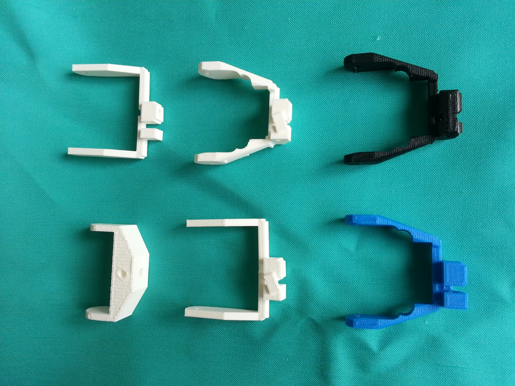
The first iteration, going from top left in the image, was a quick test of whether the idea actually makes sense. Its quite bulky but proved that we could distribute the weight evenly between the servo arm and a fixed point on the base (which you can see a bit below.) Elongated arms in the second version are the result of placing the arm on the furthest edge from the rotation point rather than the closest. This lets the servo hide entirely under the pleated textile rather than be outside of it in order to move it.
The next major change came in the fourth iteration, here the hash angles were cut in order to allow for a wider range of textile scales. Before the 90º corners would push on the pleated fabric when opened fully. Finally in the last two iterations the head of the bracket was raised in order to accommodate the thickness of the fabric. Before it was positioned at an ideal 0º point which can’t be reached when fabric is put into consideration.
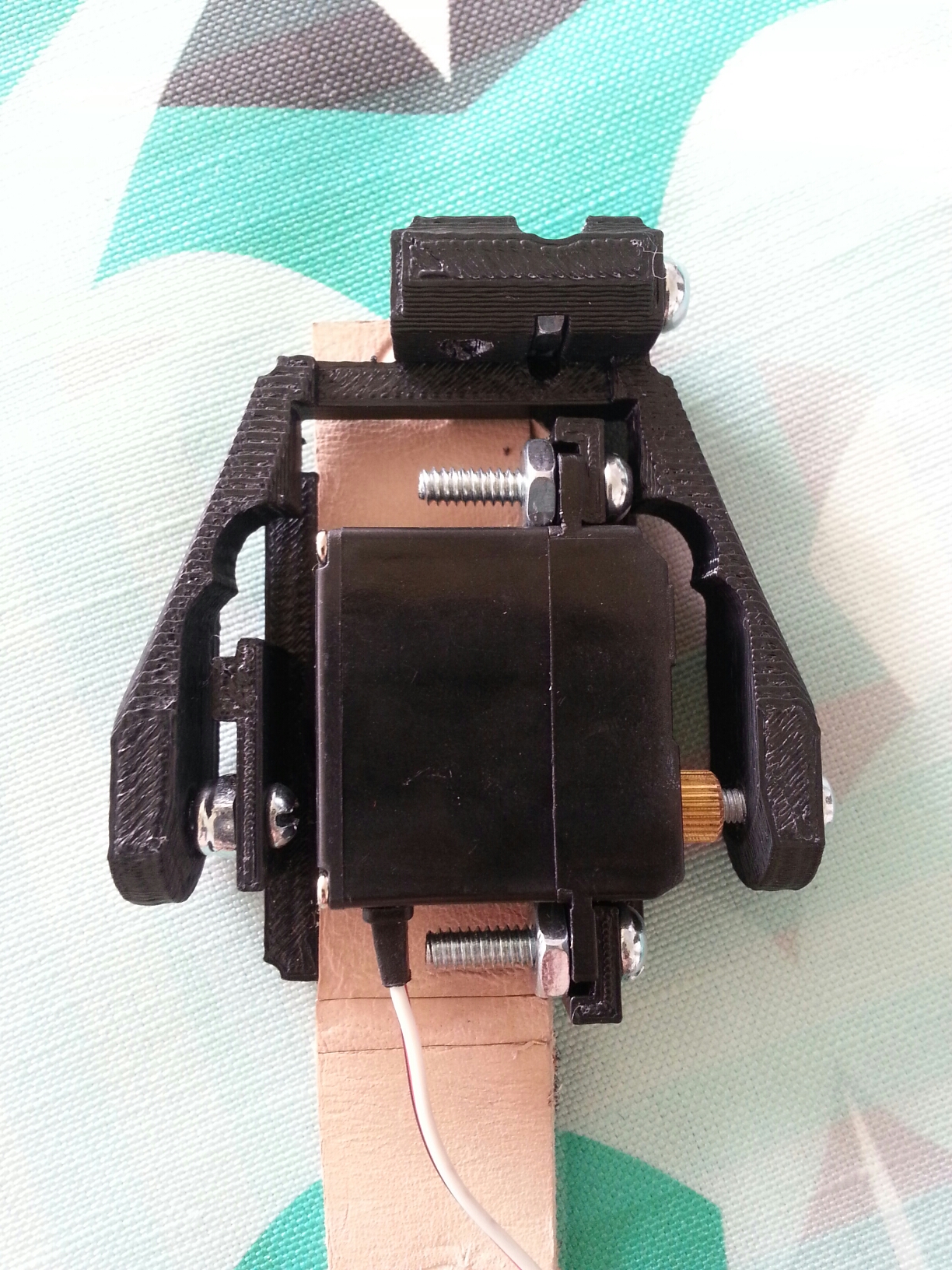
The last iteration also provides 2mm at the base in order to place a layer of vibration absorbing material. It helps reduce the noise produced by the motor in motion.


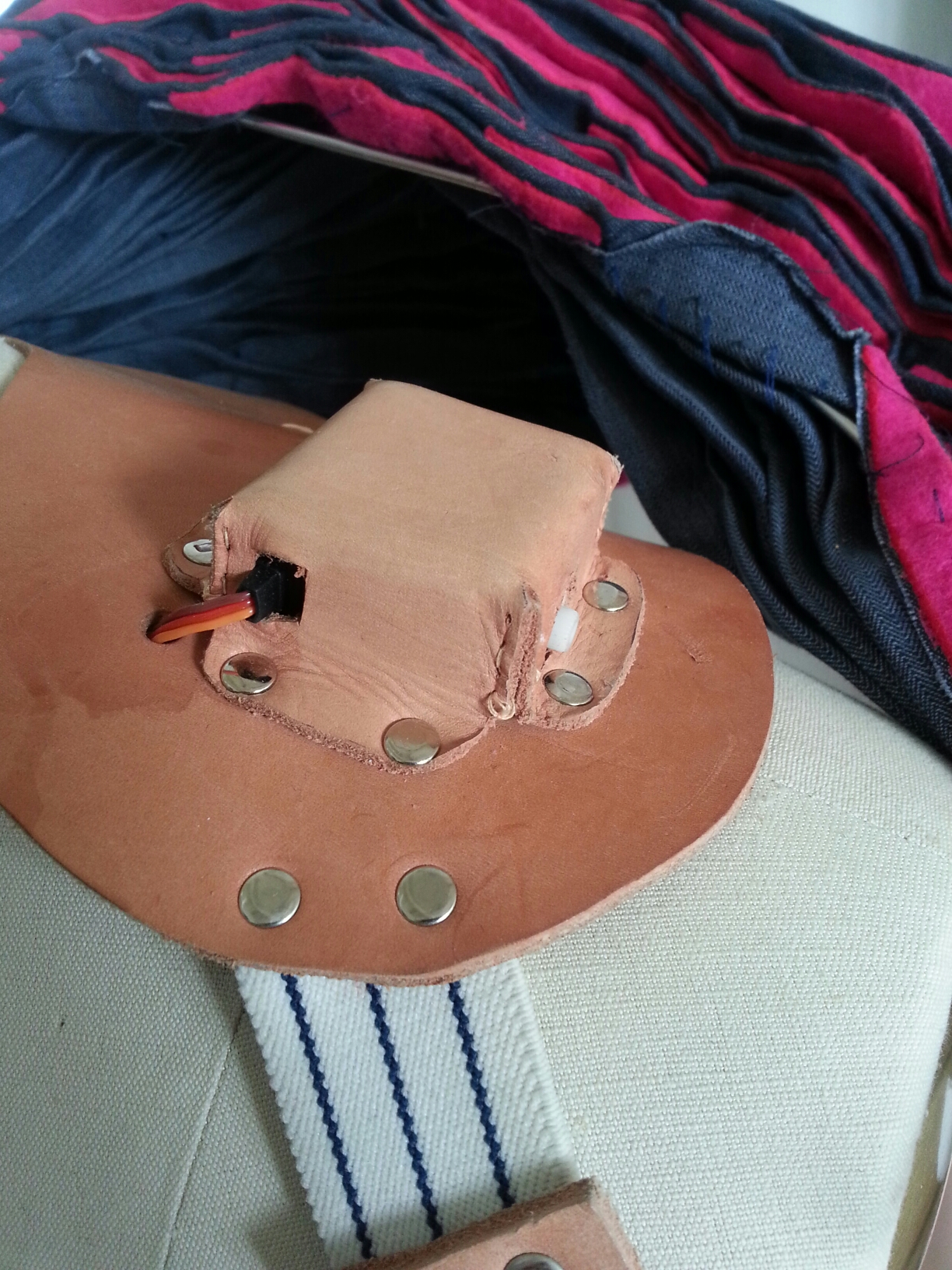
Above you can see the final design of the servo base, which allows for a secure way to snap the servo to the leather harness. The rest show the assembled construction. As a note, the scoring in the leather of the last image is a way to bend the attaching strap under the leather of the harness, letting the servo sit closer to the neck.
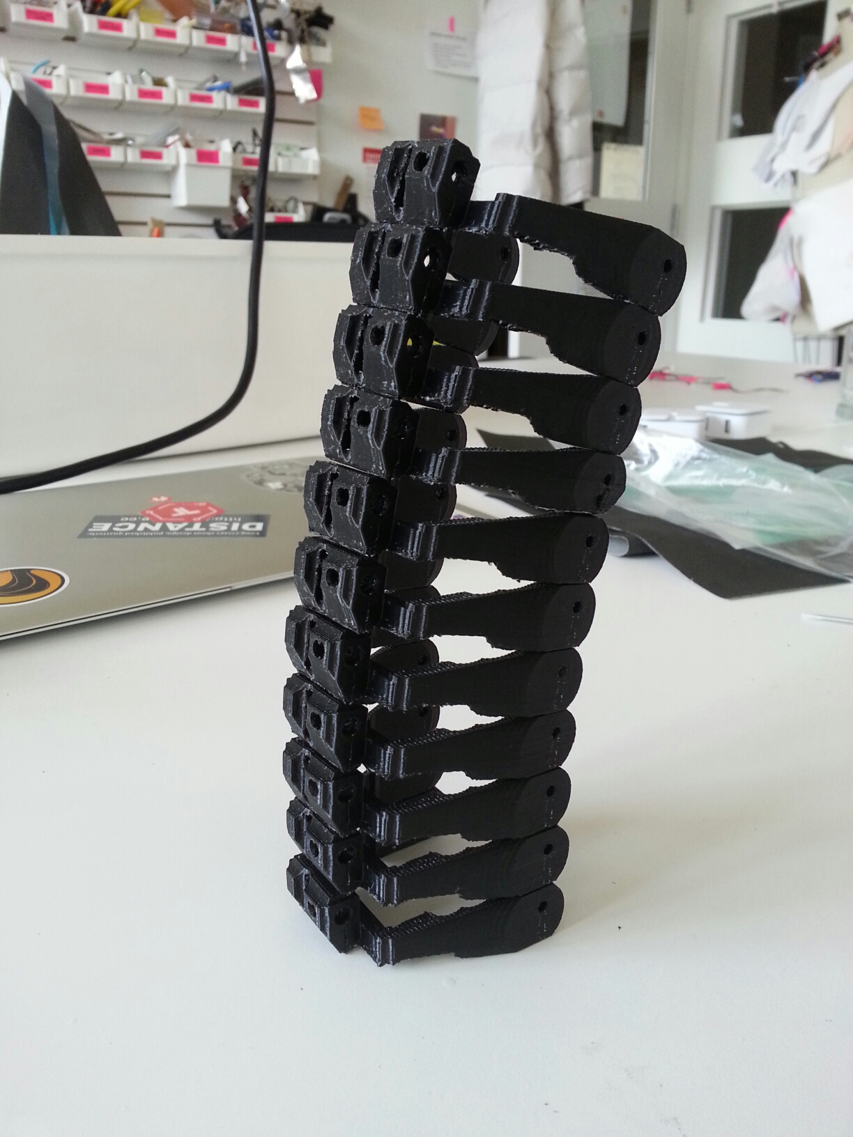
Thank you for reading, and enjoy the following tower of brackets.
One thought on “Designing a servo mount and bracket”